This article is a Chinese translation version of Vertex displacement with a noise function using GLSL and three.js by Jaume Sanchez.
如果翻译中有谬误之处,请不吝指正~
Terms | 术语
- Vertex shader:顶点着色器
- Fragment shader:片元着色器
- attribute变量:只能出现在顶点着色器中,只能被声明为全局变量,被用来表示逐顶点的信息。
- uniform变量:可以用在顶点着色器和片元着色器中,且必须是全局变量。
- varying变量:必须是全局变量,它的任务是从顶点着色器向片元着色器传输数据。
- vec2:GLSL的矢量类型,具有2个浮点数元素的矢量
- Perlin Noise:Perlin噪声,指由Ken Perlin发明的自然噪声生成算法。
- Ken Perlin:发明Perlin噪声的大神。
Vertex displacement with a noise function using GLSL and three.js | 在GLSL和three.js中通过噪点函数实现顶点位移
文章发表于2012年12月10日
阅读时间:10分钟
主题: WebGL, GLSL, three.js, shaders
这篇教程展示了创作一个带有形体变形动画的过程:使用一个球体作为基本几何体,使用perlin噪点对球体顶点位置扰乱。同时也教授了如何在扰乱上添加更多的变化以及如何添加着色。本文在Fireball explosion示例为基础写就,此示例是Experiments with Perlin Noise Series博文中的部分内容。
我使用three.js创建几何体并配置场景,但GLSL代码可以在任何其他WebGL/OpenGL的库中运行。我可以肯定它也能相当直接的转换成HLSL代码。

我将在本教程中假定你已经掌握了一定程度的WebGL知识或其他你偏爱的同类3D库的知识。在这个示例中,我将使用three.js。我使用three.js编写必要的代码来配置场景,但不会做过多的讲解。市面上已经有很多此类示例和文档了。您可能需要先查看本文的示例链接,我会尽量保证本示例非常基础。
Creating the scene: a sphere and a camera | 创建场景:一个球体和一个摄像机
在开始前我们需要做几件事,包括:引入three.js,然后创建renderer,scene,camera,material和mesh。我们的scene将包含mesh和camera,并且camera镜头将会正对mesh。如果你要使用键盘或鼠标控制摄像机的移动,你可以查看本文中的其中任何一个示例代码是怎么做的。
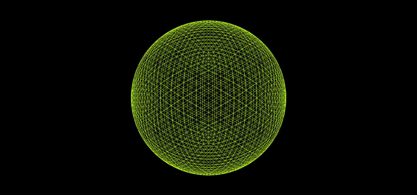
我们将使用球体几何体来创建mesh,因为使用它能很方便满足我们的需求。在我们进行更复杂的着色前,可以把material暂时设置为线框着色器。带有鲜艳颜色的线框是调试3D的好帮手。
以下是起步阶段的代码:
// Basic page | 基础页面
// HTML - index.html | index.html页面中的HTML代码

<!doctype html>
<html lang="en">
  <head>
    <title>Perlin noise | Fireball explosion</title>
    <meta charset="utf-8">
  </head>

  <body>
    <div id="container"></div>
  </body>

  <script src="js/three.min.js"></script>

  <script type="x-shader/x-vertex" id="vertexShader">
  // Put the Vertex Shader code here | 在这里放置顶点着色器代码
  </script>

  <script type="x-shader/x-vertex" id="fragmentShader">
  // Put the Fragment Shader code here | 在这里放置片元着色器代码
  </script>

  <script type="text/javascript" id="mainCode">
  // Put the main code here | 在这里放置主代码,即threejs代码
  </script>

</html>
然后把以下JavaScript代码添加到id为mainCode的script标签中。
// Three.js boilerplate | Three.js引用
// JavaScript - index.html | index.html页面中的JavaScript代码

var container,
    renderer,
    scene,
    camera,
    mesh,
    start = Date.now(),
    fov = 30;

window.addEventListener( 'load', function() {

  // grab the container from the DOM | 从DOM中获取id为container的div
  container = document.getElementById( "container" );

  // create a scene | 创建一个场景
  scene = new THREE.Scene();

  // create a camera the size of the browser window | 创建一个浏览器窗口大小的摄像机
  // and place it 100 units away, looking towards the center of the scene | 放置在z轴坐标100个单位处,摄像机会默认看向场景的中心
  camera = new THREE.PerspectiveCamera(
    fov,
    window.innerWidth / window.innerHeight,
    1,
    10000
  );
  camera.position.z = 100;

  // create a wireframe material | 创建一个线框材质
  material = new THREE.MeshBasicMaterial( {
    color: 0xb7ff00,
    wireframe: true
  } );

  // create a sphere and assign the material | 创建一个球体并给它指定材质
  mesh = new THREE.Mesh(
    new THREE.IcosahedronGeometry( 20, 4 ),
    material
  );
  scene.add( mesh );

  // create the renderer and attach it to the DOM | 创建一个渲染器并将它添加到DOM中
  renderer = new THREE.WebGLRenderer();
  renderer.setSize( window.innerWidth, window.innerHeight );
  renderer.setPixelRatio( window.devicePixelRatio );

  container.appendChild( renderer.domElement );

  render();

} );

function render() {

  // let there be light | 渲染输出场景
  renderer.render( scene, camera );
  requestAnimationFrame( render );

}
这样就建立了一个场景,一个位于场景中央、半径为20、由200x200个片段组成的线框球体。一个相机从z轴100个单位处观察它。尝试更改球体中的半径或线段,或将相机或网格移动到其他位置。
Creating our custom shader | 创建自定义着色器
如果我们想要玩转渲染,我们必须要学会创建自己的着色器。自定义着色器将允许我们编写所期望的顶点和片元着色器的行为方式。我们需要将material从标准的THREE.MeshBasicMaterial更改为THREE.ShaderMaterial。 THREE.ShaderMaterial有一些基本参数:vertexShader,fragmentShader和uniforms。
vertexShader:顶点操作的GLSL代码。fragmentShader:片元操作的GLSL代码。uniforms:顶点和片元着色器共享的变量所组成的对象。
将创建material的代码行(译注:上面代码中的THREE.MeshBasicMaterial)使用以下代码替换:
// Custom basic shader material | 自定义基本着色器材质
// JavaScript | JavaScript代码

material = new THREE.ShaderMaterial( {
  vertexShader: document.getElementById( 'vertexShader' ).textContent,
  fragmentShader: document.getElementById( 'fragmentShader' ).textContent
} );
上面这段代码从script标签中获取着色器代码,并将其分配到对应的着色器。Three.js会用它们组成一个完整的着色器,并传递给WebGL驱动程序进行编译。然后它就可以使用了。
将以下代码添加到id为vertexShader的script标签中。
// Basic vertex shader code | 基本顶点着色器代码
// GLSL | GLSL代码

varying vec2 vUv;

void main() {

  vUv = uv;
  gl_Position = projectionMatrix * modelViewMatrix * vec4( position, 1.0 );

}
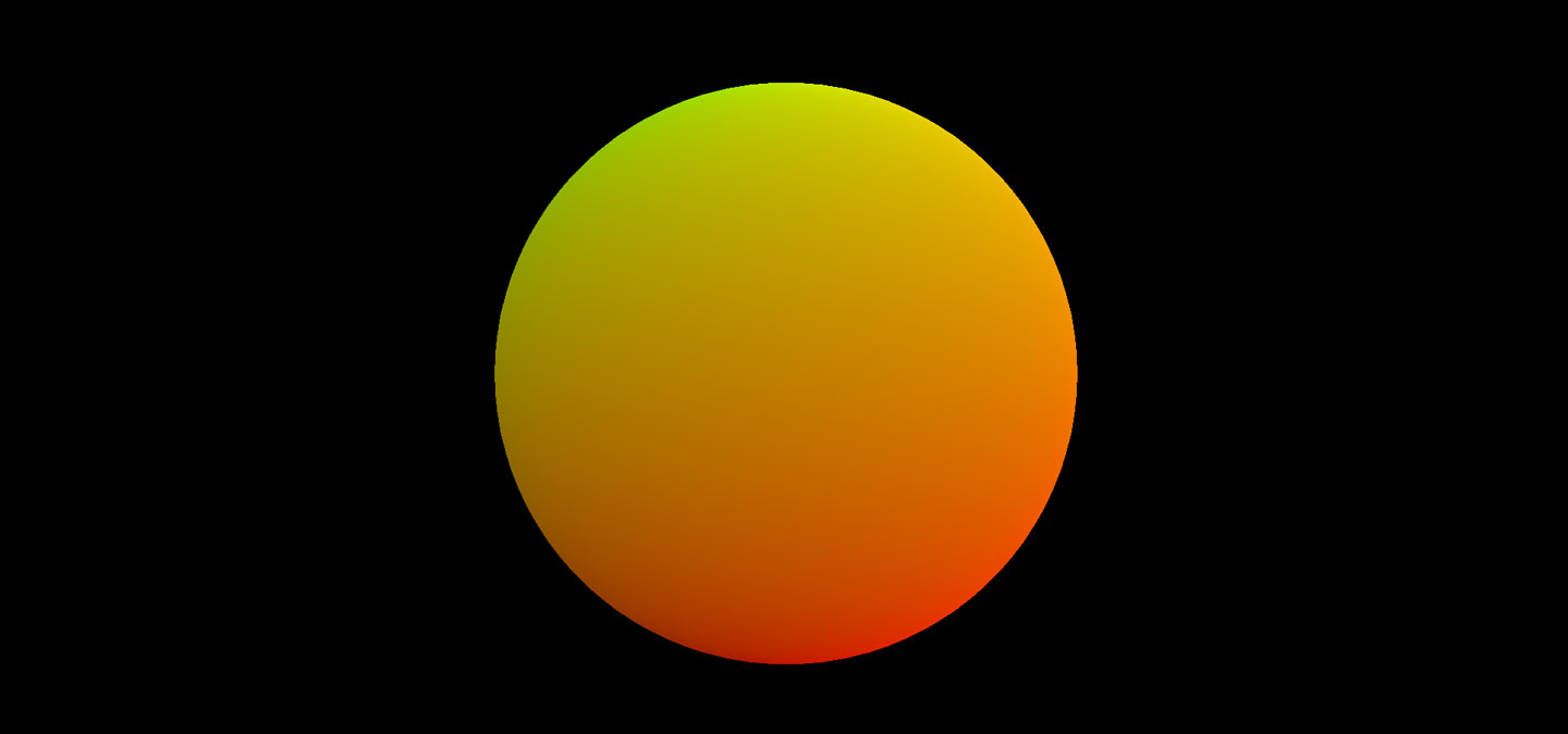
此着色器几乎是最基本的顶点着色器。它接收一个名称为uv(二维向量、或vec2类型,指定在纹理的0到1空间内读哪个纹素)的attribute变量(attribute专门给顶点着色器传递参数),并使用名为vUv(另一个vec2类型)的varying变量(varying是可以在顶点着色器和片元着色器之间共享或传递的参数)将它传递到片元着色器。它还接收了顶点position属性(position是指在对象坐标中顶点原始位置的三维向量),并执行变换以将顶点放置到眼坐标系( eye coordinates)中。当使用像SphereGeometry或IcosahedronGeometry这样的基础几何体创建网格时,这两个值(译注:此处指attribute变量uv,以及attribute变量position。)会由three.js自动创建并且传递给顶点着色器。所以你无需担心任何事情。
将以下代码添加到id为fragmentShader的script标签中。
// Basic fragment shader code | 基本片元着色器代码
// GLSL | GLSL代码

varying vec2 vUv;

void main() {

  // colour is RGBA: u, v, 0, 1 | RGBA颜色值为:u,v,0,1
  gl_FragColor = vec4( vec3( vUv, 0. ), 1. );

}
这个着色器也很简单。获取给定片元的UV坐标(顶点着色器中命名为vUv,并由GPU为每个片段插值),并将片元的UV坐标用作片元颜色的第一和第二个分量。我们可以使用纯色作为片元着色器的输出,但使用纹理坐标给对象着色可以更容易地看到项目进展情况。
Let’s make some noise! | 制造噪点
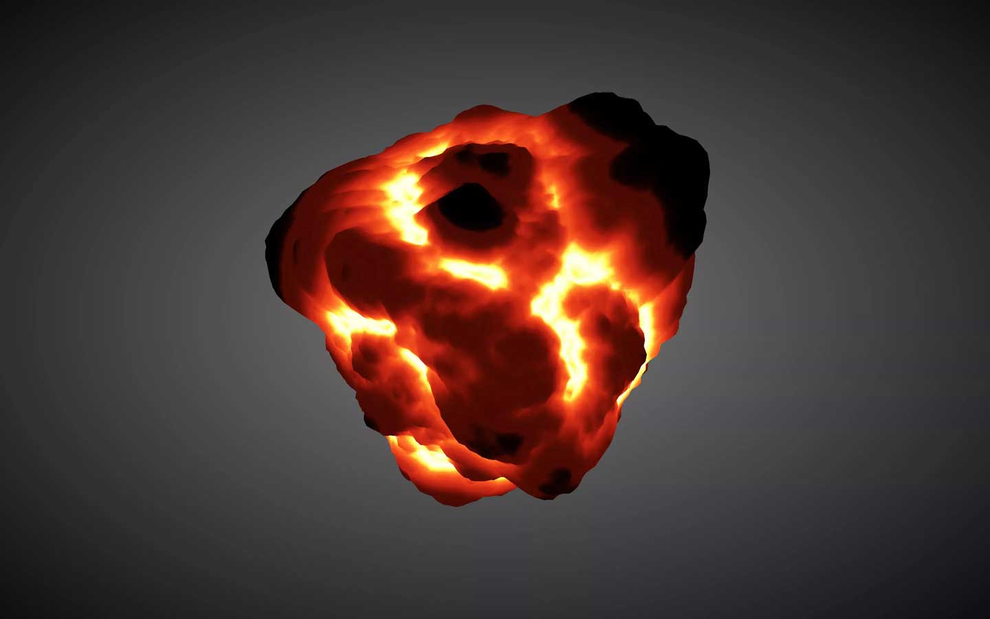
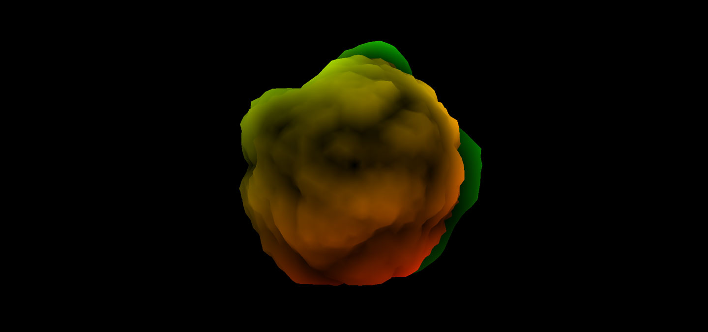
现在,终于到了有趣的部分!球体是精确的、完美无瑕的,但又极其乏味;我们将扰乱顶点位置以获得有趣的形状:土豆,团块,星星,爆炸……
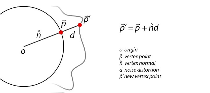
我们的主要思路是:沿着法线方向扰乱每个顶点位置。想象一下,一些线从球体的中心点出发连接至每个顶点,每个顶点都有这样的一条线。最初,所有这些线都是相同的长度(也就是球体的半径)。如果我们使一些线变长,一些线变短,我们将会获得一个有趣的、被扰乱后的网格。
随机是一个好东西,但也会造成混乱,以至于让人讨厌。我们希望扰乱有些随机但又在可控范围内,这里我们再次用到Perlin Noise来挽回局面。
我将使用ashima’s webgl-noise,这是一套极其出色且WebGL兼容的过程噪点着色程序(Procedural Noise Shader Routines)。我不打算在这里复制使用整个代码库。你必须将噪点代码添加进顶点着色器,这个噪点代码库的注释是这样说的。我们将使用Classic Noise 3D。在着色器中使用Perlin Noise有很多选择:标准实现,简单实现(译注:这边不清楚这两种实现的区别),以及噪点纹理。选择哪一个取决于噪点的用处和要求。其中的规则是越复杂计算越慢,如果您需要大量噪点值,你可以使用噪点纹理以便快速查找。
Random is good, but also chaotic and not very appealing.
随机是一个好东西,但这也会造成混乱,以至于让人讨厌。
让我们沿着法线方向扰乱顶点:我们想要将法线乘以一些缩放系数,使其可以缩放(从中心到顶点的线缩短或伸长,因为它定义了顶点位置,顶点自身向内或向外移动)。这就是我们应用噪点值的地方。噪点的坐标基于被修改前的法线,并且噪点值被调节到了适合期望的比例。我没有直接使用噪点函数(noise function),而是使用湍流函数(turbulence function)替代,由Ken Perlin提供,它创造了非常有趣的形状。我们鼓励您尝试不同的噪点函数,并为噪点函数提供不同的参数和周期。
我做了一个附加的变形,添加了一个基于较大噪点(低频噪点)的系数,以扰乱球体形状。尝试更改噪点中不同的值和b(译注:这些参数在顶点着色器中),以查看每个值如何影响生成的形状。
处理噪点函数时非常重要之处在于:您通常会传递具有时间连贯性的参数,因为您不希望网格突然改变每帧的形状。这可以通过使用一些值来实现,它对于顶点或片元的每一帧都是相同的:它可以是attribute或uniform,但我通常喜欢使用UV坐标,位置或法线。这通常在转换为眼坐标(eye coordinates)之前。
我将噪点存储,用来伪造一个环境遮挡系数。这在渲染形状时非常有用,可以在凹陷区域上突出凸起区域(译注:原文为to highlight raised regions agains sunken regions,原作者可能把against拼错成了agains)。
现在我们使用位移系数在法线方向上移动顶点,以此来计算顶点的新位置:就像取顶点的原始位置并加上法线乘以噪点一样简单。
新的顶点着色器如下所示:
// Mesh distortion - vertex shader | 网格变形 - 顶点着色器
// GLSL | GLSL代码

// Include the Ashima code here! | 在这里引入Ashima的代码(即Classic Noise 3D的GLSL代码)

varying vec2 vUv;
varying float noise;

float turbulence( vec3 p ) {

  float w = 100.0;
  float t = -.5;

  for (float f = 1.0 ; f <= 10.0 ; f++ ){
    float power = pow( 2.0, f );
    t += abs( pnoise( vec3( power * p ), vec3( 10.0, 10.0, 10.0 ) ) / power );
  }

  return t;

}

void main() {

  vUv = uv;

  // get a turbulent 3d noise using the normal, normal to high freq
  // 输入normal得出 turbulent 3d 噪点,normal to 高频
  noise = 10.0 *  -.10 * turbulence( .5 * normal );
  // get a 3d noise using the position, low frequency
  // 输入 position 得出3d噪点,低频
  float b = 5.0 * pnoise( 0.05 * position, vec3( 100.0 ) );
  // compose both noises
  // 合成两种噪点
  float displacement = - 10. * noise + b;

  // move the position along the normal and transform it
  // 沿法线移动顶点位置,使球体变形
  vec3 newPosition = position + normal * displacement;
  gl_Position = projectionMatrix * modelViewMatrix * vec4( newPosition, 1.0 );

}
这是使用环境遮挡系数的新片元着色器:
// Mesh distortion - fragment shader | 网格变形 - 片元着色器
// GLSL | GLSL代码

varying vec2 vUv;
varying float noise;

void main() {

  // compose the colour using the UV coordinate
  // 使用uv坐标生成颜色
  // and modulate it with the noise like ambient occlusion
  // 将 noise 作为环境遮挡,调整片元颜色
  vec3 color = vec3( vUv * ( 1. - 2. * noise ), 0.0 );
  gl_FragColor = vec4( color.rgb, 1.0 );

}
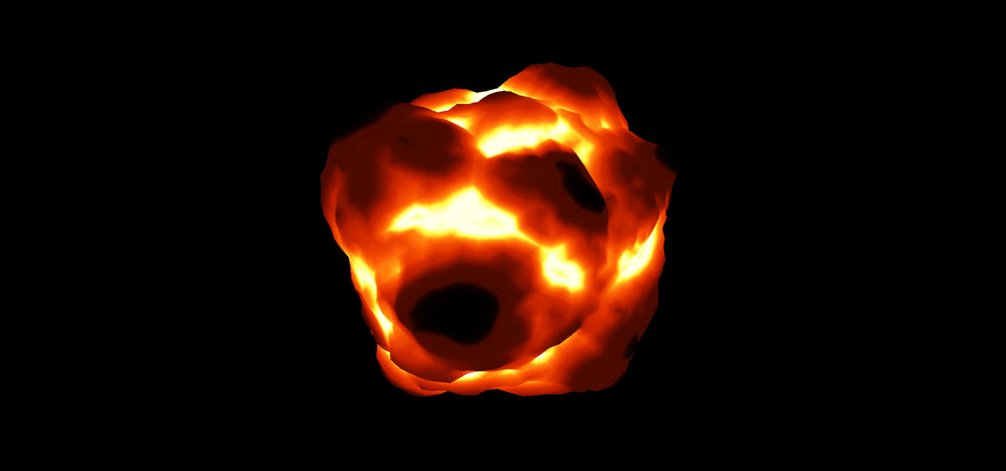
Add some colour, and movement! | 添加一些颜色和运动
离最终效果越来越近了。它开始看起来像是那么回事了。
让我们添加一些颜色。我们可以编写一个函数,它使用几个插值器来创建一个从暗到亮的渐变,由红色,橙色和亮黄色组成。如果有其他选择,我通常不喜欢花费不必要的时间处理资产(译注:作者的意思用GLSL写这个效果会很花时间,不如用一张图片)。在这个示例中,我去google images,寻找爆炸图片,选择我最喜欢的图片,然后从图片上切割一片具有正确渐变的图像。
现在我们有了爆炸的图像,我们必须将它传递给着色器才能使用。这是在JavaScript中完成的,我们必须修改我们之前创建的ShaderMaterial。我们添加一个定义纹理的uniform(2D采样器)。我们还添加了一个时间系数来为爆炸制作动画。记住所有用于uniform类型的three.js约定不是一件容易的事:Uniform types一个好帮手(译注:原文中的此链接已经失效,可以访问这个页面查询uniform types)。
// Custom shader material for texturing | 自定义用于纹理的着色器材质
// JavaScript | JavaScript代码

material = new THREE.ShaderMaterial( {

  uniforms: {
    tExplosion: {
      type: "t",
      value: THREE.ImageUtils.loadTexture( 'explosion.png' )
    },
    time: { // float initialized to 0
      type: "f",
      value: 0.0
    }
  },
  vertexShader: document.getElementById( 'vertexShader' ).textContent,
  fragmentShader: document.getElementById( 'fragmentShader' ).textContent

} );
我已经更新了代码,使用新的three.js表示法来指定uniforms中的纹理。
我们在render函数中添加进首先要做的事,即需要更新uniforms中指定的时间变量。
// Passing time value to shader | 将时间值传递进着色器
// JavaScript | JavaScript代码

material.uniforms[ 'time' ].value = .00025 * ( Date.now() - start );
最终的顶点着色器几乎相同,但我们在噪点中添加了一个时间系数,因此顶点会随着时间的推移而移动。
// Mesh distortion over time - vertex shader | 网格随着时间推移而变形 - 顶点着色器
// GLSL | GLSL代码

// Include the Ashima code here!

varying vec2 vUv;
varying float noise;
uniform float time;

float turbulence( vec3 p ) {

  float w = 100.0;
  float t = -.5;

  for (float f = 1.0 ; f <= 10.0 ; f++ ){
    float power = pow( 2.0, f );
    t += abs( pnoise( vec3( power * p ), vec3( 10.0, 10.0, 10.0 ) ) / power );
  }

  return t;

}

void main() {

  vUv = uv;

  // add time to the noise parameters so it's animated | 将时间添加到噪点中使它动起来
  noise = 10.0 *  -.10 * turbulence( .5 * normal + time );
  float b = 5.0 * pnoise( 0.05 * position + vec3( 2.0 * time ), vec3( 100.0 ) );
  float displacement = - noise + b;

  vec3 newPosition = position + normal * displacement;
  gl_Position = projectionMatrix * modelViewMatrix * vec4( newPosition, 1.0 );

}
这是最终的片元着色器,根据深度对纹理进行采样以确定颜色。它还包含了一个随机函数,以稍微打破渐变,使其看起来更自然。
// Mesh distortion over time - fragment shader | 网格随着时间推移而变形 - 片元着色器
// GLSL | GLSL语言

varying vec2 vUv;
varying float noise;
uniform sampler2D tExplosion;

float random( vec3 scale, float seed ){
  return fract( sin( dot( gl_FragCoord.xyz + seed, scale ) ) * 43758.5453 + seed ) ;
}

void main() {

  // get a random offset | 获取随机偏移
  float r = .01 * random( vec3( 12.9898, 78.233, 151.7182 ), 0.0 );
  // lookup vertically in the texture, using noise and offset | 垂直方向上查找纹理,使用噪点和偏移
  // to get the right RGB colour | 获取正确的RGB色值
  vec2 tPos = vec2( 0, 1.3 * noise + r );
  vec4 color = texture2D( tExplosion, tPos );

  gl_FragColor = vec4( color.rgb, 1.0 );

}
Wrapping up | 总结
基本上这就是使用多项式(polynomials)改变网格的开端(译注:不确定翻译的是否准确。原文为 This is basically all there is to start altering a mesh with polynomials)。从现在开始,天空就是极限。顶点位移可以使用可读取的2D或3D纹理来实现;顶点位移可以沿法线或切线;顶点也可以缩放、扭曲、调整、倒置……
请注意,法线并没有被正确计算以应用到光线中(译注:猜测这里作者表达的意思是法线没有被真正正确的计算,所以在光照下,无法用这个法线模拟出正确的凹凸效果。):我们只是沿着原始球体形状的法线进行了扰乱。它没有根据我们新创建出的形状来更新法线。在这个示例中,这点无关紧要,因为物体是自发光的,100%自发光。对于复杂照明,必须计算正确的法线。
Nobody gets those values right the first time, it’s all after much tinkering and iterating.
没有人能在第一次就获得正确的值,只有在经过无数次修补和迭代之后才能获得。
如果你对许多“随机”的值感到疑惑,不要认为它们是魔术、或无法理解的数字。在获得正确的外观和感觉之前,所有的一切都需要进行实验。
我可以向你保证,没有人能够在第一时间获得正确的值,都是在经过无数次修补和迭代之后才获得的。事实上,很多实验得到的是一个完全不同且意想不到的结果。所以不要绝望。你可能会失去一个火球,但你可能会赢得一个……粘糊糊的西兰花?。
您可以看到使用这种简单技术在其他示例中的应用:Experiments with Perlin Noise Series,或者一个更精致的例子:It’s a Halloween Message。
一如既往,欢迎质疑和改进建议。尽情享受乐趣吧!
Interpreted by Xie Huating, 2019-04-29